Task 1: Voltage Signal Attenuation
When looking back at the voltage measurement for the battery, we realise that there is much to be improved with the circuit that we came up with so far. Therefore, we looked into ways of improving the circuit of the voltage measurement, while improving the accuracy of our measurements.
Thus, we have looked into one of the suggestions given by our lecturers, to use a current sensor and a resistor to be connected in parallel with the SunSPEC 4's motor. This would thus omit the danger for shorting the high voltage and low voltage sides, while allowing us to implement circuits that boosts the sensor's sensitivity.
Figure 1 would show the circuit diagram. Note that the circuit does not include the solar panels as a power source, as we want to show the measurement of the battery voltage.
 |
| Figure 1. Voltage Sensing Circuit Diagram |
Task 2: Current Amplifier
After connecting the current sensor and resistor in parallel with the car's motor, we are implementing a circuit that boosts the current sensor's sensitivity. In Figure 2 below, the V1 is referring to the current sensor's output.
 |
| Figure 2. Current Amplifier Circuit Diagram |
Task 3: Current Calibration
The current sensor that we got is a hall-effect sensor. We tested it out to obtain the sensitivity and accuracy of the sensor. The power supply can supply 0 - 3.25 ampers. Thus, we experimented and obtain readings for every 0.1A.
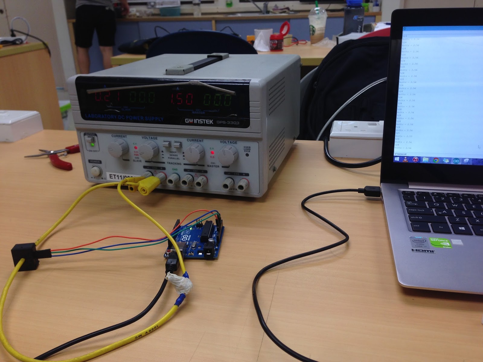 |
| Figure 3. Set up of current calibration |
 |
| Figure 4. Voltage - Current Graph |
From our experiment, we noticed a change of 0.01V for every 0.1A change. The sensitivity of the sensor is roughly 100mV/A, which is much higher than our initial current sensor. However, the loop is very small and fits up to AWG12 only. We still have to look into other sensors as motor and battery side requires AWG8.