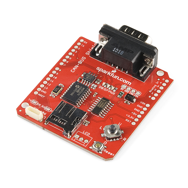
Task 1: CANBUS - Ethernet Testing
The Ethernet Shield was tested in order to verify that communication can be done in the CAN bus system.
We tested the Ethernet shield to check if we can connect the Arduino to a specific IP address. Therefore, when we key the IP address of the Arduino code into our web browser, we would be able to see the readings for the analog pins.
The IP address would be of a similar range to the IP address of the router that we are using. The figure below would show the results that we have obtained from testing the Ethernet Shield
 |
| Figure 1. Ethernet Shield Testing Results |
Task 2: Logging GPS Coordinates
This week, we managed to get the GPS module EM406 talking to the satellite. Testing was done at various locations to ensure that the GPS coordinates are accurate. The accuracy of GPS module depends on the location that we are at. It was difficult to obtain accurate coordinates indoors as the satellite was not communicating well with EM406. Thus, It would show an "INVALID" on our serial port as shown below.
 |
| Figure 2. GPS Tracking Program and Serial Output |
We were able to obtain the accurate readings once we are in open air and the module is communicating with the satellite. When moving, the coordinates also changes. The date and time logged by the GPS module is GMT timing. This means that during the actual race, we would have to convert the time to Australia timing.
In order to get the GPS program to run, the tinyGPS++ library have to be installed. Appendix is our program for testing the module.
#include <TinyGPS++.h> //include this library for the GPS to work
#include <SoftwareSerial.h> //this is the GPS software serial library
// Choose two Arduino pins to use for software serial
// The GPS Shield uses D2 and D3 by default when in DLINE mode
int RXPin = 2;
int TXPin = 3;
// uses 4800 baud by default
int GPSBaud = 4800;
// Create a TinyGPS++ object called "gps"
TinyGPSPlus gps;
// Create a software serial port called "gpsSerial"
SoftwareSerial gpsSerial(RXPin, TXPin);
void setup()
{
// Start the Arduino hardware serial port at 9600 baud
Serial.begin(9600);
// Start the software serial port at the GPS's default baud
gpsSerial.begin(GPSBaud);
Serial.println(F("DeviceExample.ino"));
Serial.println(F("A simple demonstration of TinyGPS++ with an attached GPS module"));
Serial.print(F("Testing TinyGPS++ library v. ")); Serial.println(TinyGPSPlus::libraryVersion());
Serial.println(F("by Mikal Hart"));
Serial.println();
}
void loop()
{
// This sketch displays information every time a new sentence is correctly encoded.
while (gpsSerial.available() > 0)
if (gps.encode(gpsSerial.read()))
displayInfo();
// If 5000 milliseconds pass and there are no characters coming in
// over the software serial port, show a "No GPS detected" error
if (millis() > 5000 && gps.charsProcessed() < 10)
{
Serial.println(F("No GPS detected"));
while(true);
}
}
void displayInfo()
{
Serial.print(F("Location: "));
if (gps.location.isValid())
{
Serial.print(gps.location.lat(), 6);
Serial.print(F(","));
Serial.print(gps.location.lng(), 6);
}
else
{
Serial.print(F("INVALID"));
}
Serial.print(F(" Date/Time: "));
if (gps.date.isValid())
{
Serial.print(gps.date.month());
Serial.print(F("/"));
Serial.print(gps.date.day());
Serial.print(F("/"));
Serial.print(gps.date.year());
}
else
{
Serial.print(F("INVALID"));
}
Serial.print(F(" "));
if (gps.time.isValid())
{
if (gps.time.hour() < 10) Serial.print(F("0"));
Serial.print(gps.time.hour());
Serial.print(F(":"));
if (gps.time.minute() < 10) Serial.print(F("0"));
Serial.print(gps.time.minute());
Serial.print(F(":"));
if (gps.time.second() < 10) Serial.print(F("0"));
Serial.print(gps.time.second());
Serial.print(F("."));
if (gps.time.centisecond() < 10) Serial.print(F("0"));
Serial.print(gps.time.centisecond());
}
else
{
Serial.print(F("INVALID"));
}
Serial.println();
}
We hope to get GPS coordinates and have it displayed on DAQ so that we can save the file for analysis.